16.2 My first QM/MM job
Contents
In this section, we illustrate a QM/MM MD simulation of alanine tripeptide (Ala3) in solution using density functional tight binding (DFTB). Let’s download the tutorial file (tutorial19-16.2.zip or github). This tutorial contains five directories.
$ unzip tutorial19-16.2.zip
$ cd tutorial-16.2
$ ls
1_dftb/   2_system/   3_qmmm/   4_analysis/   toppar/
1. DFTB+
We will use DFTB+ in this tutorial. The program is available free of charge from the website, dftbplus.org. DFTB calculations require a set of parameters for each atoms, which are stored in the so-called Slater-Koster (SK) files. The files are available from dftb.org. Note that some parameters are suitable for organic/bio molecules (3ob), whereas others are developed for materials science (matsci). Also, the available elements are different among the parameter sets. See the download page for more details. Here, we will use the 3ob parameters and carry out DFTB3 calculations for Ala3. We assume that you have installed DFTB+ and downloaded the 3ob files in you computer.
1_dftb directory contains two files,
$ cd 1_dftb
$ ls
dftb_01.hsd  runDFTB.sh
These files correspond to qmcnt and qmexe illustrated in section 16.1. dftb_01.hsd is a template file to create an input file for DFTB+, and runDFTB.sh is a file to invoke DFTB+. Let’s look into these files in more details.
All the input parameters for DFTB+ must be present in dftb_01.hsd except for the Geometry section (QM coordinates) and the ElectricField section (MM coordinates), which are supplemented by GENESIS in runtime.
Hamiltonian = DFTB {
   SCC                = Yes                        (1)
   Charge             = 0.0                        (2)
   ReadInitialCharges = Yes                        (3)
   SlaterKosterFiles  = Type2FileNames {
     Prefix = "/path/to/dftb/slako/3ob-3-1/"       (4)
     Separator = "-"
     Suffix = ".skf"
   }
   MaxAngularMomentum {
     H = "s"                                       (5)
     C = "p"
     N = "p"
     O = "p"
   }
   Filling = Fermi {
     Temperature [Kelvin] = 0.0
   }
 }

 Analysis = {
   CalculateForces = Yes                           (6)
 }
(1) Perform self-consistent charge (SCC) DFTB.
(2) The charge of the QM system, Ala3, is set to zero.
(3) Restart from the previous SCC charge.
(4) Change “/path/to” to the directory of your SK files.
(5) Specify the atoms in Ala3.
(6) We need the forces in addition to the energy.
As for runDFTB.sh, the path to DFTB+ must be specified in the first part of the file shown below.
# -----------------------------------------------
# Settings for DFTB+
#
# --- Set the path for DFTB+ ---
export PATH=/path/to/dftbplus-18.1/_install/bin:$PATH   (1)

# (optional)
# --- Set a file to read initial charges ---
# initial='../charges.bin_save'                         (2)
(1) Specify the path to the bin directory of DFTB+.
(2) Optionally, specify a SCC charge file obtained in the previous step. In the first step, the DFTB job restarts using the SCC charge contained in this file.
The rest of the file can be used as is, unless you have special reasons to make a change.
2. Ala3 in a water-sphere
2_system directory contains the pdb/crd and psf of a system, i.e., Ala3 in water.
$ cd 2_system
$ ls
snapshot50.crd  snapshot50.pdb  snapshot50.psf  snapshot50.vmd
The system can be visualized using VMD,
$ vmd -e snapshot50.vmd

You will find a cluster system, where the solute, Ala3, is located in the center of a sphere surrounded by a layer of water molecules of 20 Å thickness. The current version of GENESIS does not support periodic boundary condition (PBC) for QM/MM, and thus QM/MM must be carried out in noBC using a cluster system. In Section 16.3, we will illustrate how to prepare such systems.
3. QM/MM calculation
Let’s move into a directory of QM/MM calculations:
$ cd 3_qmmm/
$ ls
qmmm_min.inp  qmmm_nvt.inp  qmmm_nvt.vmd  script.sh
qmmm_min.inp and qmmm_nvt.inp are control files to perform minimization and MD, respectively. The control parameters are the same as the previous ones (see tutorial 3.2, for example), so we only describe the parameters that are specific to QM/MM calculations. There are two important points.
3.1. Setting up a QM/MM potential
The first is, of course, to specify a QM/MM potential. The potential is controlled by [ENERGY] and [QMMM] sections. The [ENERGY] section sets the parameters for the MM force field. Currently, CHARMM force field is the only option, though we plan to make AMBER force field available very soon.
[ENERGY]
forcefield          = CHARMM
electrostatic       = CUTOFF       (1)
switchdist          = 16.0         (2)
cutoffdist          = 18.0
pairlistdist        = 19.5
vdw_force_switch    = YES
(1) CUTOFF must be specified for noBC instead of PME.
(2) A longer cutoff length is recommended than in PME.
The [QMMM] section controls QM calculations.
[QMMM]
qmtyp               = dftb+                      (1)
qmcnt               = ../1_dftb/dftb_01.hsd      (2)
qmexe               = ../1_dftb/runDFTB.sh
qmatm_select_index  = 1                          (3)
workdir             = /dev/shm/qmmm_min          (4)
savedir             = qmmm_min                   (5)
basename            = job                        (6)
qmsave_period       = 10                         (7)
qmmaxtrial          = 1                          (8)

[SELECTION]
group1  = segid:PROA                             (3)
group2  = atomno:19
(1) Use DFTB+.
(2) A template input file and a run script file for DFTB+.
(3) QM atoms (=Ala3) are specified using the selector.
(4) A working directory where input/output of QM jobs are written/read.
(5) A directory where QM files are stored.
(6) The basename of QM files.
(7) The frequency to save QM files.
(8) When the QM job fails, GENESIS restarts the job up to this number of iteration.
In the above example, DFTB calculations are carried out for Ala3 (42 atoms) surrounded by point charges (MM atoms). The input and output files of DFTB+ are created in a directory specified by workdir. Because DFTB is quite fast, it is recommended to use a fast disk, such as RAM disk, NVMe-SSD, etc, so as to avoid any file I/O bottleneck. The DFTB+ files are then copied and saved in a directory savedir every 10 steps.
3.2. Setting up a spherical potential
Secondly, we setup a spherical potential. This is needed for simulations in noBC, since otherwise the (water) molecules at the boundary may evaporate and run away to infinity. The spherical potential has no effect on atoms that are inside of the sphere, but pulls back those that went out of the sphere. The functional form of the potential reads,
\( \displaystyle V_{sph} = k_{const} \left( r – r_b \right )^n \ (r \geq r_b), \\ \displaystyle \hspace{16pt} = 0 \ (r < r_b), \)
where \( r \) is a distance from the center, and \( k_{const}\) and \( r_b \) are the force constant and the radius of the sphere, respectively. We specify the parameters in the [BOUNDARY] section as follow,
[BOUNDARY]
type          = NOBC
spherical_pot        = yes           (1)
constant             = 10.0          (2)
exponent             = 2             (3)
nindex               = 1             (4)
center_select_index1 = 2             (5)
radius1              = 20.0          (6)
fix_layer            = 1.0           (7)

[SELECTION]
group1  = segid:PROA
group2  = atomno:19                  (5)
(1) invoke the spherical potential.
(2) \( k_{const}\) in kcal/mol/Å2.
(3) The exponent of the potential. Usually, “2” is recommended.
(4) The number of spheres.
(5) The center of the sphere specified by the selector.
(6) The radius of a sphere in Å.
(7) The thickness of a layer of fixed atoms.
In this example, a spherical potential with a radius of 20 Å is created around the 19th atom (CA of Ala3). Note that the center does NOT follow the motion of the CA atom. The position of the CA atom is referred only once at the beginning, and the center of the sphere is kept fixed during the simulation. The atoms that are out of the sphere in the initial structure (snapshot50.crd) are kept fixed. Furthermore, a layer of fixed atom can be controlled using fix_layer. In the above example, the atoms that are farther than 19 Å from the center are kept fixed.
The information of the potential and the fixed atoms is written in a restart file. Thus, in the subsequent calculations (e.g., qmmm_nvt.inp), the same potential is applied by reading a restart file in the [INPUT] section and setting spherical_pot = yes in the [BOUNDARY] section.
[INPUT]
rstfile = qmmm_min.rst

[BOUNDARY]
 type          = NOBC
 spherical_pot = yes
 restart       = yes
3.3 Running a QM/MM job
We are now ready to run the job. script.sh is a bash script to run the job. Here, we assume that the computer has 16 cores per node, and that we want to run a job with (16 thread x 1MPI). In order to run a 16-thread job, we set an environment variable,
export OMP_NUM_THREADS=16
export  QM_NUM_THREADS=16
OMP_NUM_THREADS is for GENESIS/atdyn and QM_NUM_THREADS is for a QM program. Usually, they are set to be the same number.
In OpenMPI (since around 1.10), the process is bound to a single core by default when the number of MPI processes is ≤ 2. Therefore, a simple command
mpirun -np 1 atdyn qmmm_min.inp >& qmmm_min.out
would be carried out using only one core, thereby being extremely slow. To avoid this issue, one needs to specify the mapping of cores to each MPI processes. For example, --map-by node:pe=N assigns N process element (cores) in a node to each MPI processes, and is suitable for the present purpose.
mpirun -np 1 --map-by node:pe=${QM_NUM_THREADS} atdyn qmmm_min.inp >& qmmm_min.out
mpirun -np 1 --map-by node:pe=${QM_NUM_THREADS} atdyn qmmm_nvt.inp >& qmmm_nvt.out
There are alternatives such as -bind-to socket (to run the job using 1 CPU); consult the manual of OpenMPI for further details. It is a good practice to add -display-map to monitor the mapping of cores to each MPI processes.
In IntelMPI, there is no such complexity, and the following command should work.
mpirun -np 1 -ppn 1 atdyn qmmm_min.inp >& qmmm_min.out
mpirun -np 1 -ppn 1 atdyn qmmm_nvt.inp >& qmmm_nvt.out
Now type the following command to run the job,
$ chmod +x script.sh ../1_dftb/runDFTB.sh
$ ./script.sh
Upon successful run, you will find the following message in output files (qmmm_min.out and qmmm_nvt.out) showing that 42 atoms of Ala3 are selected as QM atoms,
Setup_QMMM> Setup QM region
QM assignment info
1  PROA 1 ALA CAY CT3 assigned to QM atom 1  of element: C 6
2  PROA 1 ALA HY1 HA3 assigned to QM atom 2  of element: H 1
3  PROA 1 ALA HY2 HA3 assigned to QM atom 3  of element: H 1
4  PROA 1 ALA HY3 HA3 assigned to QM atom 4  of element: H 1
...
42 PROA 3 ALA HT3 HA3 assigned to QM atom 42 of element: H 1
number of QM atoms = 42
The input/output files of DFTB+ are found in qmmm_min.0 and qmmm_nvt.0 directories,
$ ls qmmm_min.0
job0.inp   job0.log   job0_charges.bin   job0_detailed.out
job10.inp  job10.log  job10_charges.bin  job10_detailed.out
...
The minimization will finish in 5 minutes, but the MD simulation will take 4 hours or so. Grab a coffee and get relaxed!
When the MD is finished, the resulting trajectory, qmmm_nvt.dcd, can be visualized using VMD,
$ vmd -e qmmm_nvt.vmd
You will see that Ala3 and water molecules in the central region propagate in time, while the water molecules in the outlayer are kept fixed.
4. Analysis
The analysis can be done in the same was as in the previous section (see tutorial 3.2, for example). In 4_analysis directory, there are two script files,
$ cd 4_analysis
$ ls
minimize.gpi  minimize.sh*  temp.gpi      temp.sh*
$ ./minimize.sh
$ ./temp.sh
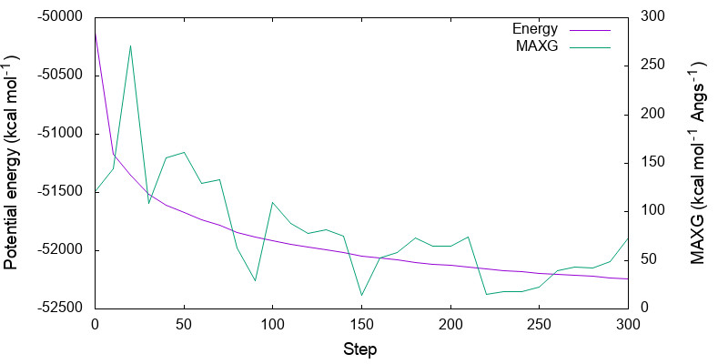
The command creates minimize.pdf and temp.pdf. The former shows the variation of the energy and maximum gradient along the minimization step,

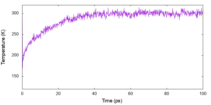
and the latter gives the variation of temperature along the simulation time,

Written by Kiyoshi Yagi@RIKEN Theoretical molecular science laboratory
Dec., 5, 2020
