How to make a simulation movie with PyMol?
Contents
Computational biophysicists often show simulation movies in their oral presentations at seminars, conferences, and so on. In order to show a movie in a presentation, you need to create a movie file from MD trajectories and embed it in your presentation slides. In this tutorial, we will explain how to output images of molecular structures in MD trajectories using PyMol, one of the famous molecular viewers in the field of structural biology, and how to create a movie file by combining these images. We will use the convert and ffmpeg commands as well as GENESIS. The convert command is available in the Imagemagick software package. These tools should be installed before this tutorial.
Outline
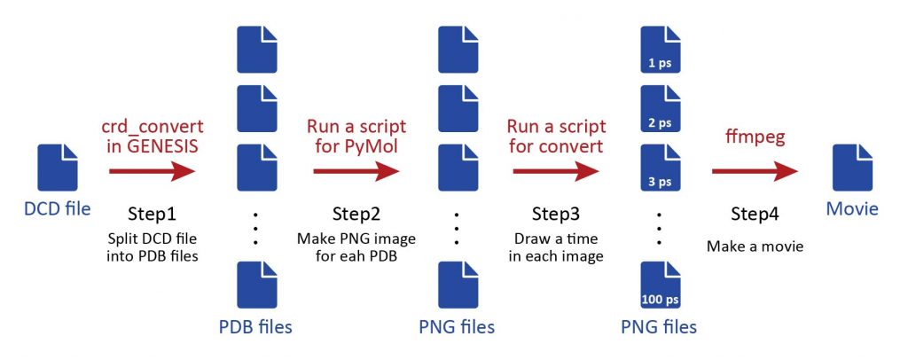
The scheme consists of four steps shown in the figure below: In Step1, the DCD file obtained from the MD simulation is split into individual PDB files using the GENESIS crd_convert tool. In Step2, PyMol is run with a script to create png images of each snapshot. In Step3, run the convert command again with a script to write the simulation time to each image. Finally, in Step4, use the ffmpeg command to combine all the images and create a move file.
Preparation
Let’s download the PDB and DCD sample files (tutorial19-appendix1.zip) for this tutorial. This is the MD trajectory of a small protein, and the trajectory contains 100 frames. The sample does not contain any water molecules, but you can use the same protocol even if solvent is explicitly present. The input and script files for each step are already included in the respective directories.
# Download the tutorial file
$ cd ~/GENESIS_Tutorials-2019/Works
$ mv ~/Downloads/tutorial19-appendix1.zip ./
$ unzip tutorial19-appendix1.zip

# Clean up the working directory
$ mv tutorial19-appendix1.zip ./TRASH

$ cd appendix1
$ ln -s ../../Programs/genesis-1.7.1/bin ./
1_makepdb  2_makepng  3_convert  4_ffmpeg  Data  bin

# Check the trajectory data and initial structure
$ ls ./Data/
md.dcd  proa.pdb
Step1. Create individual PDB files from the DCD file
First, we will split the DCD file into individual PDB files using the GENESIS crd_convert tool. Before we run the tool, let’s take a look at the control file.
# Change the directory for Step1
$ cd 1_makepdb

# Take a look at the control file of crd_convert
$ less INP
[OUTPUT]
pdbfile = md0.pdb
trjfile = md{}.pdb

[OPTION]
trjout_format  = PDB                # (PDB/DCD)
trjout_type    = COOR+BOX           # (COOR/COOR+BOX)
trjout_atom    = 2                  # atom group
split_trjpdb   = YES                # output split PDB trajectory
The most important options in the control file are shown above and colored in red: “split_trjpdb = YES” and “trjout_format = PDB” in the [OPTION] section, and “trjfile = md{}.pdb” in the [OUTPUT] section. The index of the snapshot will be inserted in parentheses in the output file name. Let’s execute the crd_convert tool to this control file.
# Run the crd_convert tool
$ ../bin/crd_convert INP > log
$ ls
INP       md2.pdb   md33.pdb  md47.pdb  md60.pdb  md74.pdb  md88.pdb
log       md20.pdb  md34.pdb  md48.pdb  md61.pdb  md75.pdb  md89.pdb
md0.pdb   md21.pdb  md35.pdb  md49.pdb  md62.pdb  md76.pdb  md9.pdb
md1.pdb   md22.pdb  md36.pdb  md5.pdb   md63.pdb  md77.pdb  md90.pdb
md10.pdb  md23.pdb  md37.pdb  md50.pdb  md64.pdb  md78.pdb  md91.pdb
:
Step2. Create an image file for each snapshot
In Step2, we will execute PyMol to all the PDB files generated in Step1. In the Step2 directory, there are three files input_0.pml, template.pml, and Make.csh. First, let’s take a look at input_0.pml. This is a short PyMol script, which just reads ../1_makepdb/md0.pdb. Execute PyMol using this script.
# Change the directory for Step2
$ cd ../2_makepng
$ ls
Make.csh  input_0.pml  template.pml

# Take a look at the PyMol script for md0.pdb
$ less input_0.pml

# Run PyMol
$ pymol input_0.pml
Rotate the molecule in the PyMol window to determine the orientation of the molecule you like. Then, press the “Get View” button in the upper right corner, and you will see that matrix-like values are output in the terminal or in the upper window. These values are actually corresponding to the rotation matrix, position of the camera, and so on. We will use these values later.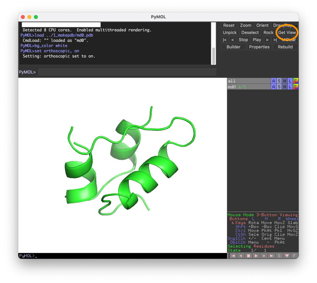
set_view (\
     0.700811803,    0.321628720,   -0.636726499,\
    -0.506851256,    0.852599680,   -0.127194136,\
     0.501961410,    0.411864907,    0.760529041,\
    -0.000017758,   -0.000041828, -106.357391357,\
   -18.747209549,    0.224934518,   -8.418970108,\
    86.687660217,  126.027915955,   20.000000000 )
Next, let’s take a look at template.pml. By using this file as a template, we will make a new PyMol script file (input_all.pml; see below) that will output an image for all PDB files. In template.pml, you will find the strings AAA and BBB, which will be replaced later by Make.csh with the indexes of the PDB file. In the middle part of the file, we write the set_view (...), which is corresponding to the above values. The width and height of a PNG image are specified by the variables width and height, respectively. Feel free to edit template.pml for your favorite representation by yourselves (see PyMol manual).
# Take a look at the script
$ less template.pml
# Set view
width  = 480
height = 480
cmd.viewport(width, height)
bg_color white
set ray_shadow, off
set ray_opaque_background, on

set_view (\
     0.700811803,    0.321628720,   -0.636726499,\
    -0.506851256,    0.852599680,   -0.127194136,\
     0.501961410,    0.411864907,    0.760529041,\
    -0.000017758,   -0.000041828, -106.357391357,\
   -18.747209549,    0.224934518,   -8.418970108,\
    86.687660217,  126.027915955,   20.000000000 )
Next, let’s take a look at Make.csh. Here, the variables ista and iend represent the first and last indexes of the PDB file where we create the image. You can also see that there is a “while” statement, which is an iterative loop that replaces the strings AAA and BBB in template.pml with the PDB indexes, and writes them to a single file input_all.pml.
# Take a look at the script for making input_all.pml
$ less Make.csh
#!/bin/csh

set ista = 0
set iend = 100

echo -n > input_all.pml
@ i = $ista
while ($i <= $iend)
  set IDX = `echo "$i" | awk '{printf("%04d",$1)}'`
  sed -e "s/AAA/$i/g" template.pml | sed -e "s/BBB/$IDX/g" >> input_all.pml
  @ i = $i + 1
end
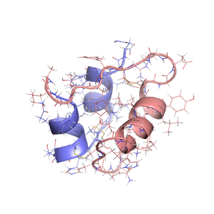
Let’s run Make.csh and take a look at the generated input_all.pml. You can see that template.pml is actually copied as a template in input_all.pml, where the commands to load md0.pdb to md100.pdb and output their images are written. Finally, let’s execute PyMol for input_all.pml with the -c option (command line mode). You will get the image files md0000.png through md0100.png.
# Run the script
$ ./Make.csh
$ ls
Make.csh  input_0.pml  input_all.pml  template.pml

# Check the PyMol script
$ less input_all.pml

# Run PyMol
$ pymol -c input_all.pml

$ ls
Make.csh       md0015.png  md0033.png  md0051.png  md0069.png  md0087.png
input_0.pml    md0016.png  md0034.png  md0052.png  md0070.png  md0088.png
input_all.pml  md0017.png  md0035.png  md0053.png  md0071.png  md0089.png
md0000.png     md0018.png  md0036.png  md0054.png  md0072.png  md0090.png
md0001.png     md0019.png  md0037.png  md0055.png  md0073.png  md0091.png
:
md0100.png
Step3. Write a simulation time in each image
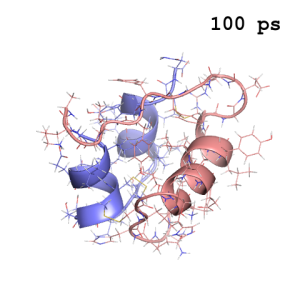
In Step 3, we will write the simulation time in the image. Displaying the time of each snapshot helps the viewer to understand the time line of the simulation video. Here, we will use a script again to handle a large number of image files. If you take a look at Run.csh in the Step3 directory, you can see that it executes the convert command on all the PNG files.
# Change directory for Step3
$ cd ../3_convert
$ ls
Run.csh

# Take a look at the script
$ less Run.csh
#!/bin/csh

set ista = 0
set iend = 100

@ i = $ista
while ($i <= $iend)
  set IDX    = `echo "$i" | awk '{printf("%04d",$1)}'`

  # Calculate the simulation time of each snapshot
  set simtim = `echo "$i" | awk '{printf("%3d",$1)}'`

  echo "IDX = $IDX simtim = $simtim"

  # run the convert command
  convert -font Nimbus-Mono-Bold -pointsize 32 \
          -gravity northeast -fill "black"     \
          -draw "text 30,20 '${simtim} ps'"    \
          ../2_makepng/md$IDX.png md$IDX.png

  @ i = $i + 1
end
The options of the convert command determine what characters are drawn in the image and how they are drawn. Here, we draw the simulation time ($simtim) in the upper right corner (-gravity northeast). Since monospaced fonts are convenient for time display, we select “Nimbus-Mono-Bold” (to see the available fonts, type “convert -list font” on the command line). In this example, the time is the same as the “snapshot index”. In other cases, you will need to calculate the correct simtim in the awk command (e.g., awk '{printf("%5.1f",$1*1.5)}', if the time interval is 1.5 ps) or something similar.
# Run the script
$ ./Run.csh
$ ls
Run.csh     md0016.png  md0033.png  md0050.png  md0067.png  md0084.png
md0000.png  md0017.png  md0034.png  md0051.png  md0068.png  md0085.png
md0001.png  md0018.png  md0035.png  md0052.png  md0069.png  md0086.png
md0002.png  md0019.png  md0036.png  md0053.png  md0070.png  md0087.png
md0003.png  md0020.png  md0037.png  md0054.png  md0071.png  md0088.png
:
md0100.png
Step4. Combine image files into a movie file
Finally, we run the ffmpeg command on the all images obtained in Step3 to create a movie file. The following is an example of creating a movie in AVI format and converting it to MP4. The resulting movie is shown below.
# Change directory for Step4
$ cd ../4_ffmpeg

# Run the ffmpeg command
$ ffmpeg -i ../3_convert/md%4d.png -qscale 0 -vcodec mjpeg -s 480x480 md.avi

# Convert the file format from avi to mp4 (if needed)
$ ffmpeg -i md.avi -b 4000k -vcodec libx264 -pix_fmt yuv420p md.mp4
Written by Takaharu Mori@RIKEN Theoretical molecular science laboratory
Feb 25, 2022