7. Power control function
7.1. Overview
The supercomputer Fugaku has a power control function (power saving function) during job execution settings are made to save power. The power available to the system is finite, and if the value expected by the operation side is exceeded during job execution, the power consumption may be reduced by forcibly reducing the CPU clock used by the job.
User can proceed the change when submitting a job or executing a job depending on the job characteristic. Settable item is called “Power knob” and the setting operation is called “Power knob operation”.
The following power knob values are set as default.
Power knob name |
Descripiton |
Setting value (Default) |
|---|---|---|
freq |
CPU frequency (MHz) |
2200 (Boost mode) |
throttling_state |
HBM memory access limit |
0 (No limit) |
issue_state |
Computing core direction issuing limit |
0 (No limit) |
ex_pipe_state |
Computing core’s number of EX |
0 (No limit) |
eco_state |
Computing core ecomode status |
2 : Use only On and FLA |
retention_state |
Computing core Retention status transition availability |
|
retention_state_acores |
Assistant core (other than core 0) Retention status transition availability |
0 (Does not transition to Retention) |
Note
Note1: The default value of retention_state is set as follows depending on the node size of the job.
Node size of the job
setting value (default)
the ability to change
9216 nodes or fewer
1 (trasition to Retention state)
able to change
9217 nodes or more
0 (do not trasition to Retention state)
unable to change
If retention_state is “1 (trasition to Retention state)”, the state transitions to a lower power state (Retention State) when no processes are running on the core. If the core is in the Retention state, it takes approximately 3ms to transition to the Run state.
Attention
Compute nodes that also serve as IO (CN/BIO, CN/ SIO, CN/GIO) are set with an emphasis on performance. The power knob value is set as follows.
For power knobs that cannot be changed, the power knob specification at the time of job submission is ignored, and a change in the Power API results in an error.
Power knob name
Descripiton
Setting value
the ability to change
freq
CPU frequency (MHz)
2200 (Boost mode)
unable to change
throttling_state
HBM memory access limit
0 (No limit)
unable to change
issue_state
Computing core direction issuing limit
0 (No limit)
able to change
ex_pipe_state
Computing core’s number of EX
0 (No limit)
able to change
eco_state
Computing core ecomode status
2 : Use only On and FLA
able to change
retention_state
Computing core Retention status transition availability
0 (Does not transition to Retention)
Only jobs with 9216 nodes or less can be changed.
retention_state_acores
Assistant core (other than core 0) Retention status transition availability
0 (Does not transition to Retention)
unable to change
Please refer to I/O node for the IO node identification.
7.2. Power mode (Power knob operation at job submisson)
It is possible to direct the power knob use when submitting a job.
7.2.1. Function overview
User can proceed the power knob operation when submitting a job. By specifying the power knob name and power knob value as a custom resource with the -L option or -rsc-list option of the pjsub command, the job is executed with the specified power knob value from the start of job execution.
$ pjsub -L "<Power knob name>=<Power knob value>" job.sh
Describing the controrable power knob by the user below.
Power knob name |
Description |
Specifiable power knob value |
Default value |
|---|---|---|---|
freq |
CPU frequency (MHz) |
2000 : Normal mode
2200 : Boost mode
|
2200
※Maximum performance
|
throttling_state |
HBM access restriction |
0:No restriction
1:90% of the number of requests
2:80% of the number of requests
3:70% of the number of requests
4:60% of the number of requests
5:50% of the number of requests
6:40% of the number of requests
7:30% of the number of requests
8:20% of the number of requests
9:10% of the number of requests
|
0
※Maximum performance
|
issue_state |
Instruction issue restriction for computing cores |
0 : 4 instructions
1 : 2 instructions
|
0
※Maximum performance
|
ex_pipe_state |
Number of compute core EXes |
0 : Use AB
1 : Use only A
|
0
※Maximum performance
|
eco_state |
Eco mode state of computing cores |
0 : Use Off, FLAB
1 : Use only Off and FLA
2 : Use only On and FLA
|
2 |
retention_state |
Retention state |
0: do not transition to Retention state
1: transition to Retention state
|
7.2.2. Use example
This indicates the power knob operation example when submitting a job.
Submit a job using 48 nodes as Boost mode and Eco mode enabled (default)
$ pjsub -L "node=48,freq=2200,eco_state=2" job.sh
At this case, the following power knob value is used before job execution starts.
Power knob name
Adopted value at job execution
freq
2200 (Boost mode)
throttling_state
0 (No limit)
issue_state
0 (No limit)
ex_pipe_state
0 (No limit)
eco_state
2 (On, only use FLA)
retention_state
retention_state_acores
0 (Non Retention)
Submit a job using 48 nodes as Normal mode
$ pjsub -L "node=48,freq=2000,eco_state=0" job.shIf proceeded changing of number of CPU frequency and power knob operation, the following power knob value is used as an initial value when job execution.
Power knob name
Adopted value at job execution
freq
2000 (Normal mode)
throttling_state
0 (No limit)
issue_state
0 (No limit)
ex_pipe_state
0 (No limit)
eco_state
0 (No limit)
retention_state
retention_state_acores
0 (Non Retention)
Submit a job using 48 nodes as Normal mode and Eco mode enabled
$ pjsub -L "node=48,freq=2000,eco_state=2" job.sh
At this case, the following power knob value is used before job execution starts.
Power knob name
Adopted value at job execution
freq
2000 (Normal mode)
throttling_state
0 (No limit)
issue_state
0 (No limit)
ex_pipe_state
0 (No limit)
eco_state
2 (On, only use FLA)
retention_state
retention_state_acores
0 (Non Retention)
Submit a job using 12 nodes as Boost mode [1]
$ pjsub -L "node=12,freq=2200,eco_state=0" job.sh
At this case, the following power knob value is used before job execution starts.
Power knob name
Adopted value at job execution
freq
2200 (Boost mode)
throttling_state
0 (No limit)
issue_state
0 (No limit)
ex_pipe_state
0 (No limit)
eco_state
0 (No limit)
retention_state
retention_state_acores
0 (Non Retention)
Execute by specifying in the job execution script
#!/bin/sh -x
#PJM -L "node=2x2x2"               # Assign node format 2x2x2 nodes (3D format)
#PJM -L "elapse=01:00:00"          # Running time limit 1h
#PJM -L "freq=2200"                # CPU clock specification
#PJM -L "eco_state=2"              # Eco mode setting
#PJM --mpi "shape=2x2x2"           # Process format 2x2x2
#PJM --mpi "max-proc-per-node=4"   # Upper limit value of number of MPI process created each node
#PJM -g groupname                  # group name
#PJM -x PJM_LLIO_GFSCACHE=/vol000N # volume names that job uses
#PJM -s                            # Output statistic information
#

mpiexec ./a.out                    # Execute a.out
Submit a job using 192 nodes as disabled computing core Retention transition
$ pjsub -L "node=192,retention_state=0" job.sh
Attention
When executed in Boost mode, the possibility of exceeding the power consumption threshold set on the system side increases. If the threshold is exceeded, the CPU frequency will be kept lower than in Normal mode. If this control is activated, the date and time of the excess will be displayed in ‘POWER CAPPING DATE’ displayed by the pjstat -s command. If not, the date and time display will be-.
7.3. Power API
At Supercomputer Fugaku, power API to proceed power measurement and control is provided. By executing a program using the Power API as a job, the user can measure and control the power of the job.
7.3.1. Function overview
User can proceed the power knob operation during job execution. At Supercomputer Fugaku, it has a power measurement and control interface using the Power API, and the power knob can be operated by describing the Power API function in C language or Fortran programs. Also it is possible to measure the electricity at that time.
Avaiable Power API at Supercomputer Fugaku is the expanded one of version 2.0, published at Sandia National Laboratories.
See also
- To see the detail of Power API, please refer to the web page of Sandia National Laboratories.
About the specific Supercomputer Fugaku information, please refer to the manual “Job Operation Software API user’s Guide for Power API”.
7.3.2. How to create Power API program
Here explains about how to create Power API program.
7.3.2.1. The flow of creating Power API program
Basic flow of Power API program is as following.
Initialization
Obtain the target of power measurement and control Object
Conduct power measurement and control for the target program section
Finalization
See also
In the Power API, devices that are targets of power measurement and control are called Objects.
7.3.2.2. Power API Initialization
By calling initialization function PWR_CntxtInit(), initialize Power API.
By initialization, obtain Power API context.
Specifiable PWR_CntxtType and PWR_Role to PWR_CntxtInit() function argument is as following.
PWR_CntxtType
Description
PWR_CNTXT_DEFAULT
Power API standard function is available to use
PWR_CNTXT_FX1000(FX1000)
Extention function for Supercomputer Fugaku compute node is available to use
Note
To PWR_Role, PWR_ROLE_APP is only specifiable that means application user.
7.3.2.3. Obtain Object
In the Power API, a device that is the target of power measurement and control is called an Object. The target system of Power API is represented by the object tree of the compute node. Obtain an Object to specify the device for power control / measurement in Power API. Each node in the object tree of the compute node indicates an Object.
Supercomputer Fugaku compute node’s Object tree
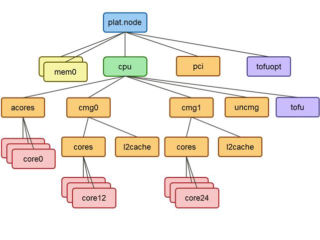
Each object’s detail is as following.
Object at Supercomputer Fugaku compute node
PWR_ObjType |
Unique name |
Description |
|---|---|---|
PWR_OBJ_NODE |
plat.node |
Whole of node |
PWR_OBJ_SOCKET |
plat.node.cpu |
CPU Socket |
PWR_OBJ_MEM |
plat.node.memN (N = 0, 1, 2, 3) |
Memory |
PWR_OBJ_POWER_PLANE |
plat.node.pci |
PCI express |
PWR_OBJ_NIC |
plat.node.tofuopt |
Optical module |
PWR_OBJ_POWER_PLANE |
plat.node.cpu.uncmg |
Excluding assistant cores, CMG, and Tofu in CPU |
PWR_OBJ_POWER_PLANE |
plat.node.cpu.acores |
Assisitant core group |
PWR_OBJ_POWER_PLANE |
plat.node.cpu.cmgN
(N = 0, 1, 2, 3)
|
CMG |
PWR_OBJ_NIC |
plat.node.cpu.tofu |
Tofu |
PWR_OBJ_CORE |
plat.node.cpu.acores.coreL
(Compute node: L = 0, 1 Compute node and I / O node: L = 0-3)
|
Assistant core |
PWR_OBJ_POWER_PLANE |
plat.node.cpu.cmgN.cores |
compute core group in CMG |
PWR_OBJ_POWER_PLANE |
plat.node.cpu.cmgN.cores.l2cache |
L2 cashe |
PWR_OBJ_CORE |
plat.node.cpu.cmgN.cores.coreM
(M = 12 to 59) There are 12 cores per CMG.
M is a serial number, and the possible range of M in cmgN can be expressed by the following formula.
12(N + 1) less than M < 12(N + 2)
|
compute core |
Attention
Note that the unique name of the Object used in the Power API is expressed by arranging the names of the nodes traversing the tree starting from the root of the tree (plat.node) and separating them with “.” please.
For example, at Object tree , if the object of cores under cmg0 is expressed by a unique name, it will be plat.node.cmg0.cores.
There are 2 ways to obtain Object.
Explicitly specify the unique name of the Object
A unique name is a string that identifies an Object.
This method is effective when the unique name of the Object you want to acquire is clear in advance.
The user specifies Object’s unique name that want to get the argument of the PWR_CntxtGetObjByName function.
Proceed Object tree search
This method is effective when you do not know in advance the unique name of the Object you want to acquire, or when it is desirable not to describe system-specific expressions in the program to improve the portability of the program.
7.3.2.4. Electricity power measurement/control
At Power API, the target electricity power measurement/control type is called Attribute.
For instance, to Attribute, electricity amount and frequency is indicated. The user can measure and control electricity power by specifying Object and Attribute.
For electricity power measurement/control, following function is used.
Function
Description
PWR_ObjAttrGetValue
Obtain the value of electricity power measurement/control.
PWR_ObjAttrSetValue
Set the value of Electricity power control.
7.3.2.5. Finalization
By calling finalization function PWR_CntxtDestroy(), close Power API.
Destory obtained context by finalization.
7.3.3. Use direction Power API from within the program
Here explains about Use direction Power API from within the program.
7.3.3.1. Header file
To use Power API in program, it is required to load next header file.
File name |
Path |
|---|---|
pwr.h |
/opt/FJSVtcs/pwrm/aarch64/include |
7.3.3.2. How to compile
To create execution file, it is required to proceed including of Power API header file and linking with Power API library.
Power API is as libpwr.so.
Specify next option when compiling and linking.
Specification case |
Option |
|---|---|
When compiling |
-I/opt/FJSVtcs/pwrm/aarch64/include |
When linking |
-L/opt/FJSVtcs/pwrm/aarch64/lib64 -lpwr |
7.3.3.3. How to execute
It is not required to specify specially about Power API to job script.
#!/bin/sh
#PJM --L "node=1"
#PJM --L "rscgrp=small"
#PJM --L "elapse=3:00"
#PJM -g groupname
#PJM -x PJM_LLIO_GFSCACHE=/vol000N
#PJM -s

# execute job
./pwrget
./pwrstat
./pwrget_multi
7.3.3.4. Sample program
Two types of sample programs use the Power API: sample programs in C language and sample program in Fortran language. Sample programs in each language are placed in the following directory under the login node:
Sample programs in Fortran language:
/home/system/sample/PowerAPI/fortran
Sample programs in C language:
/home/system/sample/PowerAPI/c
Sample Program |
File Name (C Language) |
File Name (Fortran Language) |
|---|---|---|
Electrical energy measurement |
pwrget.c |
pwrget.f |
Power control |
pwrset.c |
pwrset.f03 |
Statistical information acquisition |
pwrstat.c |
pwrstat.f03 |
Electrical energy measurement of multiple Objects |
pwrget_multi.c |
pwrget_multi.f03 |
Power control of multiple Objects |
pwrset_multi.c |
pwrset_multi.f03 |
Definition of Power API functions, variables, and types in Fortran (corresponding to header file) |
- |
pwrf.f03
pwrtypesf.f03
|
Please change and compile these sample programs as appropriate after copying them to your own directory on the login node.
When compiling sample programs in C language, please specify the file name of the sample program to be compiled.
fccpx -I/opt/FJSVtcs/pwrm/aarch64/include -c pwrget.c
fccpx -L/opt/FJSVtcs/pwrm/aarch64/lib64 -lpwr -o pwrget pwrget.o
When compiling sample programs in Fortran language, please compile pwrf.f03 first, then specify the file name of the sample program to be compiled.
pwrf.f03 defines the cross-language bindings for the Power API functions required to run the Fortran sample programs. Please add definitions as needed.
frtpx -c pwrf.f03
frtpx -I/opt/FJSVtcs/pwrm/aarch64/include -c pwrget.f03
frtpx -L/opt/FJSVtcs/pwrm/aarch64/lib64 -lpwr -o pwrget pwrget.o
7.3.4. Electric power measurement point
It is possible to measure estimated and measured power types at compute node.
A hardware module that can measure power is called a power measurement point. It is decsribed with the following Attribute at Power API.
[Types of measurable power]
Attribute |
Measurement type |
Points of electric power measurement |
|---|---|---|
PWR_ATTR_ENERGY |
Estimated power |
|
PWR_ATTR_MEASURED_ENERGY |
Measured power |
|
Attention
The estimated power of the node at the compute node represents the normalized power of the job. The estimated power of the node is the sum of the estimated power of the following objects.
Compute core group in CMG + L2 Cache + Memory + Tofu + Other modules in CPU
Assistant core is used in the process other than job. The estimated power of the optical module and PCI Express varies depending on the node to which the job is assigned. Thus, not included in the estimated power of the node.
PWR_ATTR_MEASURED_ENERGY is extention Attribute at Supercomputer Fugaku compute node. Measurement is possible only when the parameter PWR_CntxtType type is set to PWR_CNTXT_FX1000 at initialization.
Attention
Understanding the interval for obtaining power-related information
- Various types of power (estimated) available within the job by PowerAPIThey are obtained when the PowerAPI is issued, so it depends on the issuing interval.The hardware refresh interval is 1 ms.
- The amount of power (measured) available within the job by PowerAPIIt is obtained when the PowerAPI is issued, so it depends on the issuing interval.The hardware refresh interval is 5 ms.
7.3.5. Power control point
Power knob is the function to set hard ware status related to compute node electric power. A hardware module that can operate the power knob is called a power control point. Compute node power knob corresponds to the following Attribute of Power API.
[Type of power knob]
Attribute |
Power knob function |
Power control point |
Description |
|---|---|---|---|
PWR_ATTR_FREQ |
Frequency change |
CPU Socket |
Limit CPU frequency.
Specifiable value is as following (Unit :Hz).
2200000000
2000000000
|
PWR_ATTR_THROTTLING_STATE |
Memory access control |
Memory |
To limit memory issue request, control memory access controller and the bus use rate in between memories.
Specifiable value is as following.
0: Bus use rate 100%
1: Bus use rate 90%
2: Bus use rate 80%
3: Bus use rate 70%
4: Bus use rate 60%
5: Bus use rate 50%
6: Bus use rate 40%
7: Bus use rate 30%
8: Bus use rate 20%
9: Bus use rate 10%
|
PWR_ATTR_ISSUE_STATE |
Order issue limit |
CPU Core |
Control numberr of order that CPU core executes at the same time.
Specifiable value is as following.
0: 4 order
1: 2 order
|
PWR_ATTR_EX_PIPE_STATE |
EXA only |
CPU core |
Control number of pipe that order that use general registers can use.
0: Use pipe A or B
1: Use only pipe A
|
PWR_ATTR_ECO_STATE |
Eco mode and FLA only mode |
CPU core |
FLA only controls the number of pipes available for FP and SIMD registers. Eco mode is a function to increase the power reduction effect when FLA only is enabled.
Specifiable value is as following.
0: Ecomode unabled, FLA only unabled
1: Ecomode unabled, FLA only enabled
2: Ecomode enabled, FLA only enabled
|
PWR_ATTR_RETENTION_STATE |
Retention mode |
CPU core |
Controls whether to transition to a lower power state (Retention state) when a process is not running on the CPU core.
Specifiable value is as following.
0: Not transit to Retention mode
1: Transit to Retention mode
|
Attention
PWR_ATTR_THROTTLING_STATE, PWR_ATTR_ISSUE_STATE, PWR_ATTR_EX_PIPE_STATE, PWR_ATTR_ECO_STATE, and PWR_ATTR_RETENTION_STATE are extended attributes on Supercomputer Fugaku compute nodes. Control is possible only when the argument PWR_CntxtType type is specified to PWR_CNTXT_FX1000 at initialization.
PWR_ATTR_RETENTION_STATE is available for jobs with 9216 nodes or fewer.
See also
By using PWR_MD_MIN and PWR_MD_MAX, the user can know the upper and lower limits of the power knob that can be set currently.
7.3.6. Note
7.3.6.1. The power amount becomes larger than the expected value when a specific state transition is performed.
It has been confirmed that the power amount does not fall below the expected value when the following state transition is performed.
PWR_ATTR_ECO_STATE(1)         : Eco mode disabled, use FLA only
     ⇩
PWR_ATTR_RETENTION_STATE(1)   : Allow transition to Retention state
     ⇩
PWR_ATTR_ECO_STATE(0)         : Eco mode disabled, use FLA and B
     ⇩
PWR_ATTR_RETENTION_STATE(1)   : Allow transition to Retention state <- Power is larger than the expected value
You can use one of the following workarounds:
Workaround 1: Do not use PWR_ATTR_ECO_STATE(1)
PWR_ATTR_ECO_STATE(0)         : Eco mode disabled, use FLA and B
     ⇩
PWR_ATTR_RETENTION_STATE(1)   : Allow transition to Retention state
     ⇩
PWR_ATTR_ECO_STATE(0)         : Eco mode disabled, use FLA and B
     ⇩
PWR_ATTR_RETENTION_STATE(1)   : Allow transition to Retention state
Workaround 2: Do not allow transition from PWR_ATTR_ECO_STATE(1) to Retention state
PWR_ATTR_ECO_STATE(1)         : Eco mode disabled, use FLA only
     ⇩
PWR_ATTR_ECO_STATE(0)         : Eco mode disabled, use FLA and B ← add 1 line
PWR_ATTR_RETENTION_STATE(1)   : Allow transition to Retention state
     ⇩
PWR_ATTR_ECO_STATE(0)         : Eco mode disabled, use FLA and B
     ⇩
PWR_ATTR_RETENTION_STATE(1)   : Allow transition to Retention state
Workaround 3: Transit PWR_ATTR_ECO_STATE(0) via PWR_ATTR_ECO_STATE(2)
PWR_ATTR_ECO_STATE(1)         : Eco mode disabled, use FLA only
     ⇩
PWR_ATTR_RETENTION_STATE(1)   : Allow transition to Retention state
     ⇩
PWR_ATTR_ECO_STATE(2)         : Eco mode enabled, use FLA only ← add 1 line
PWR_ATTR_ECO_STATE(0)         : Eco mode disabled, use FLA and B
     ⇩
PWR_ATTR_RETENTION_STATE(1)   : Allow transition to Retention state